


Who are the NMEA?
The NMEA stands for National Marine Electronics Association. In a nutshell, they’re a not-for-profit organisation whose mission is to improve data communications between marine electronics manufacturers. Read more at www.nmea.org
What is NMEA 2000?
NMEA 2000 is an open standard designed by the NMEA to help them achieve their mission by standardising the messages and connector system used for devices in the marine industry. There is a common misconception that the term ‘open standard’ means freely available when in fact it means that the standard is available to buy at a reasonable cost from their website. It is important to remember that the NMEA is not for profit (NFP) and the standards create an important source of income so that they can continue to exist.
If you want complete peace of mind when building your NMEA 2000 network you should use NMEA 2000-certified devices. Such devices have met all the NMEA requirements and have received full certification. You can view the comprehensive list of officially certified products here.
What are the advantages of NMEA 2000?
Its simple connection makes an NMEA 2000 network easy to install.
• NMEA 2000 networks are reliable. They are self-configuring and no setup is required, meaning you can easily add or remove any compatible equipment without needing to restart the network.
• Unlike NMEA 0183, having different baud rates is not an issue with NMEA 2000 networks.
• NMEA 2000 networks can allow up to 50 different compatible devices to connect to each other.
• You do not have to replace your entire NMEA 0183 network when converting to NMEA 2000. You can easily hook up to the new network whilst keeping currently installed NMEA 0183 devices using an NMEA 2000 Gateway like the NGW-1.
What are the minimum requirements for an NMEA 2000 network?
When building your NMEA 2000 network, there are some minimum requirements;
1. A fused power insertion point (an Actisense A2K-MPT-2 connected to a fused battery supply for example)
2. 2 NMEA 2000 Certified Devices plus cables and connectors to build the network
3. 2 Termination resistors
The Actisense Starter Kits provide everything you need to get to create a basic NMEA 2000 network from scratch.
The Actisense Self-contained Boat Networks also provide a ‘plug and play’ network. However, it is important to note that SBN networks cannot be expanded.
Watch our video as we guide you on how to set up a basic NMEA 2000 Network.
Physical Layer
The network connections (cabling, t-pieces etc.) make up what is known as the NMEA 2000 ‘Physical Layer’ and have been adopted by the NMEA from the DeviceNet standard, a proven robust network solution already in use by the automotive and agriculture industries (among others). DeviceNet employs a standard for cable sizes and wiring colours which keeps NMEA 2000 networking simple and DeviceNet standard connectors allow for quick and easy ‘plug & play’ networking.
Backbone
The main section of an NMEA 2000 network is known as the ‘backbone’. All NMEA 2000 devices must connect to the backbone via a T-Piece, this is known as an ‘instrument drop’. Each end of the backbone must be correctly terminated with a 120 Ohm resistor. These resistors are connected in parallel and therefore provide 60 Ohms termination resistance over the entire network.
Cable – What are the correct cable sizes for an NMEA 2000 network?
The three different sizes of NMEA 2000 certified, DeviceNet standard cabling are ‘micro’, ‘mid’ and ‘mini’.
Micro – the smallest size of cabling used for NMEA 2000 networking. Can be used to make up the backbone for smaller installations as well as instrument drops.
Mid – an intermediate size of cabling that must only be used for installing an NMEA 2000 backbone. more suitable for larger NMEA 2000 installations.
Mini – the largest size of cabling. Again, it must only be used for installing an NMEA 2000 backbone. A popular solution for larger NMEA 2000 installations.
The Actisense A2K range includes multiple options of pre-manufactured lengths of micro cable with over moulded, waterproof (IP 67 when mated), and gold-plated connectors.
100-metre reels of bulk cable, A2K-BULK-100M, are also available. When used with Actisense field fit connectors, this provides a complete solution for custom lengths of NMEA 2000-certified cable. Field fit connectors will be explained in the “Connections” section.
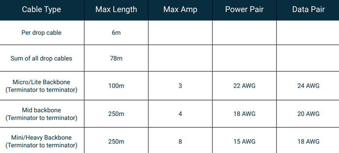
The maximum backbone and instrument drop length for each cable type can be found in the “Network Limitations” section.
Connections – Are all NMEA 2000 connectors the same?
The DeviceNet standard allows for simple ‘plug & play’ connectivity with screw-type connectors making installation quick and easy. The wiring connections to each pin on the connectors have been defined in the NMEA 2000 specification, making installation standard across NMEA 2000 installations. See the diagrams below for the pre-defined NMEA 2000 pinouts when viewed from the rear.
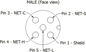 |
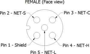 |
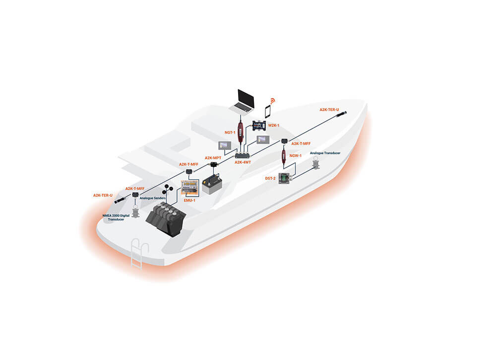
As previously mentioned, devices connect to the NMEA 2000 network via an NMEA 2000 certified T-Piece. The Actisense A2K t-pieces (A2K-T-MFF) have been designed so that devices can be easily connected even while the t-piece remains secured to a bulkhead. The gold-plated screw connectors make Actisense t-pieces durable ensuring they should last the lifetime of any NMEA 2000 installation.
In areas where up to four device connections are required, the Actisense four-way t-piece (A2K-4WT) can be used to drastically speed up installation time instead of using four individual t-pieces.
Actisense field fit connectors (A2K-FFC) are available in both male and female options as well as a right-angled variant for both gender types, perfect for installing NMEA 2000 cables in tight corners or around bends.
How to power an NMEA 2000 network
Power Insertion using A2K-MPT-2:
The Actisense Micro power T-piece has a twin pair of power wires, one for each side of the T-piece. Both pairs must be connected to a 12/24 Volt power supply (via fuse panel) so that the electrical load can be distributed evenly.
When using 24V systems, a warning must be installed on the network to ensure anyone installing new devices is aware. This is because the NMEA 2000 specification doesn’t officially support 24V but this level of power supply can be used if installed devices are capable of supporting it. All Actisense devices support 24V power supplies.
Power using A2K-SBN-1 / SBN-2:
The power cord for the Small Boat Network is over moulded to the case of a 4-way / 8-way T-piece to prevent water ingress. Power is available to all 4 / 8 ports once the pair of bare wires are connected to a 12V or 24V power supply.
Power Insertion using Quick Network Block (QNB-1):
The Actisense Quick Network Block (QNB-1) provides a versatile and easy-to-install solution for any NMEA 2000 network, utilising high-quality NMEA 2000 barrier strip connections. With glands fitted to the QNB-1, it allows for custom lengths of cable and cable mixing, meaning that the QNB can be implemented with Raymarine STNG cables for example.
The QNB-1 splits the power feed with separate fusing on either side, enabling longer networks with isolation due to the ATO fuses. The other version (QNB-1-PMW), comes with 6 x M12 Standard Female (Micro) Connectors, allowing for ‘plug and play’ with drop cables.
You will hear some common phrases used when discussing NMEA 2000 networks. Here’s what they mean:
Backbone: The main trunk of cable that runs through the boat to form the network. T-pieces are connected along the network for devices to plug into.
Drop Cable: The length of cable that connects an NMEA 20000 device to the backbone. It is important to highlight that the maximum length for a drop cable as per the NMEA 2000 standard is 6m.
PGN: Stands for ‘Parameter Group Number’. The messages used by NMEA 2000 devices for sharing information.
How do I test and diagnose my NMEA network?
Testing Power Supply and Termination Resistors
Ideally, the power supplied to the network should be tested at 2 points; the insertion point, and the extremities of the network.
Power insertion points should be tested to determine how much power is actually being supplied to the network. Any device which does not have an external power supply is powered from the backbone, thus there needs to be sufficient power to run all of the connected instruments.
The power should never exceed 14V, and be below 9V. With network devices using up some of the supplied power and impedance from cabling also dropping the voltage, it is important to know that the voltage at the end of each backbone leg is adequate.
Temporarily remove a termination resistor from the end of the network and use a voltmeter to measure across the NET-S and NET-C pins. The measured value should be at least 9V.
When testing the resistance on the network, the value expected is 60 ohms. This test can be performed by powering down the network and placing a DMM across the NET-H and NET-L pins. If 120 Ohms is measured, only one termination resistor is installed. A second resistor will need to be installed at the opposite end of the network to the one that is already present.
If 40 Ohms is observed, there are 3 termination resistors installed on the network so 1 will need to be removed. If it’s not obvious where the third resistor is, check for any devices on the network with installed termination resistors and ensure they are switched off. Network devices with termination resistors installed do not achieve NMEA 2000 certification as this practice can cause confusion on the network.
Further Testing
If the issue is still present after verifying that both the power supply and termination resistance are good, then further testing is required: A common technique used for investigating a network is to split the network into sections by moving the terminator: Disconnect one half of the backbone and move the termination resistor to the new, temporary end of the network.
If the issue remains you have narrowed it down to the half of the network that is still powered and active. If the issue does not remain it is in the half of the network that has been disconnected.
Keep performing this half-split method until you are able to narrow it down to a single device, if possible.
Don’t forget to move the termination resistor each time to ensure the network is correctly terminated. Once the issue has been narrowed down, try swapping out t-pieces or cabling with ones that are known to be good.
If Field Fit Connectors have been used, check the wiring connections inside to ensure that they are correct and firmly secured in place.
If possible, check the wiring inside the device is properly and securely terminated, ensuring to observe anti-static precautions if exposing internal electronics. It is always best to check that this is ok with the device manufacturer before performing this step to ensure you do not void any warranty.
If an issue still remains you now know there is a problem with the device and it’s time to contact the manufacturer of that device.
For a complete guide to installing your NMEA 2000 network and using Actisense products, please download our NMEA 2000 e-book.
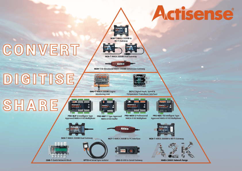
View the full range of Actisense NMEA 2000 products