


Understanding Voltage Drop Calculations
So, we’ve already covered powering your NMEA 2000 network, next we need to understand the basics behind voltages on a network, and how power supply insertion must be considered. In this article, we cover voltage drop calculations, which explains why the previous article’s fundamentals are so important.
Voltage drops are essentially the amount of voltage that is taken by devices down the backbone, in between each device and the end of the network. Voltage drops on a network are limited by the voltage available, the type of supply used, and distribution loss.
We need voltage drop calculations to ensure that all devices get enough power.
One thing to remember with voltage drop calculations is that it isn’t always the ‘last’ device on the network that will have the greatest voltage drop, rather it is the device that is farthest away from the power insertion point. (Drop cable lengths are important here).
Typically, there are 2 types of network power locations;
– End powered, where the power supply only goes one way and is found typically at the very end of the left/right-hand side of the backbone.
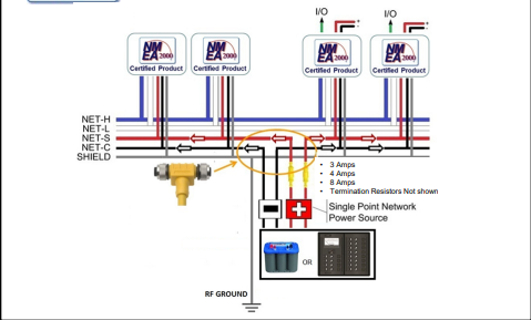
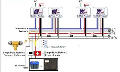
– Middle powered, where the supply is powering both left and right sides of the backbone independently, and this is located near the center of the network.
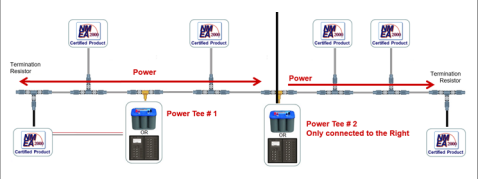
However, on large networks, there may be a requirement for multiple isolated power supplies on the backbone to ensure that every device gets sufficient power. Installing multiple supplies should be done with caution, and it is always recommended that a certified NMEA installer performs any device or power installation on your network.
If more than one power supply is required, it is essential that the direction of power is drawn out. For example, if you have 1 middle-powered supply on the network, and need more power further down the network on the right-hand side, then the second power tee should only be connected to the right-hand side.
Multiple isolated power sources MUST be the same Make and Model
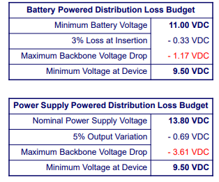
Power supplies and voltage drop calculations have a ‘loss budget’, which is the maximum backbone voltage drop that is allowed, depending on the supply type.
This is explained in the following table from the NMEA:
The NMEA Voltage Drop Calculator:
Voltage drop calculations are performed using Ohms Law, where;
E = I * R
E = Voltage Drop
I = Total Network LEN (NL)
R = Backbone Length (BL)
VD = 0.1 * NL * BL * Cable Resistance
The cable resistance varies depending on which cable is used, Lite, Mid or Heavy Cable;
Lite = 0.057 Ω / Metre
Mid = 0.015 Ω / Metre
Heavy = 0.012 Ω / Metre
In this example of a Lite Cable network;
NL = 10
BL = 12.5
Cable Resistance = 0.057
VD = 0.1 * NL * BL * Cable Resistance
VD = 0.1 * 10 * 12.5 * 0.057 = 0.71 V
An important reminder: If you have a middle-powered backbone, then the left and right side calculations need to be done separately.
Further calculations
In some installations, segment voltage drop calculations are used, especially if the voltage drop exceeds the allowed limits. This is typically where the drop exceeds 1.17V from a battery, and 3.61V when using a 13.8VDC Power supply across the network.
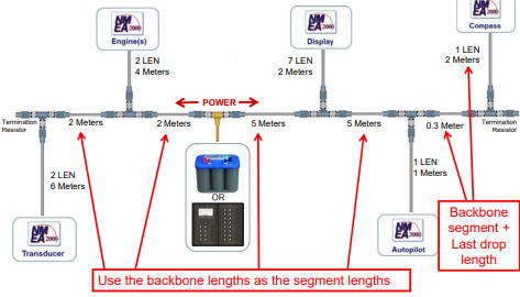
Segment voltage calculations are done by treating each part of the backbone individually and calculating the voltage drop across each segment/drop cable and the device connected to the bus at that location. These are done for a number of reasons, but the common reasons are:
The initially estimated voltage drop from the normal calculations is very close to the limit, thus detailed calculations are required to ensure that the network will operate correctly.
– If the outcome of the initial estimation is not clear, then detailed calculations are needed.
– If more flexibility is required with the installation, or if devices need to be moved around until the network‘s voltage levels are suitable.