


 | Published: November 26, 2025 | Updated: November 27, 2025
Being able to diagnose issues on your boat’s electronics network can save you a huge amount of time, money and tears later. Our Solutions Engineer, Josh Keets, shares his top recommended methods for tackling onboard diagnostics.
1. Use a Digital Multimeter (DMM) for power & resistance testing
A digital multimeter is one of the simplest, most valuable diagnostic tools. It allows you to run essential tests on the NMEA 2000 network, including:
Power Testing
- Test power at two points:
- The power insertion point
- The extremities of the backbone
- Network voltage should be between 9V and 14V.
- To test the voltage at the end of the backbone, temporarily remove a termination resistor and use a voltmeter to measure across the NET-S and NET-C pins. You should see at least 9V.
Resistance Testing
Power the network down and measure across NET-H and NET-L:
- 60 ohms → correct termination (two resistors)
- 120 ohms → only one resistor installed
- 40 ohms → three resistors installed (remove one)
If it’s not obvious where the third resistor is, check for any devices on the network with installed termination resistors and ensure they are switched off. Network devices with termination resistors installed do not achieve NMEA 2000 certification, as this practice can cause confusion on the network.
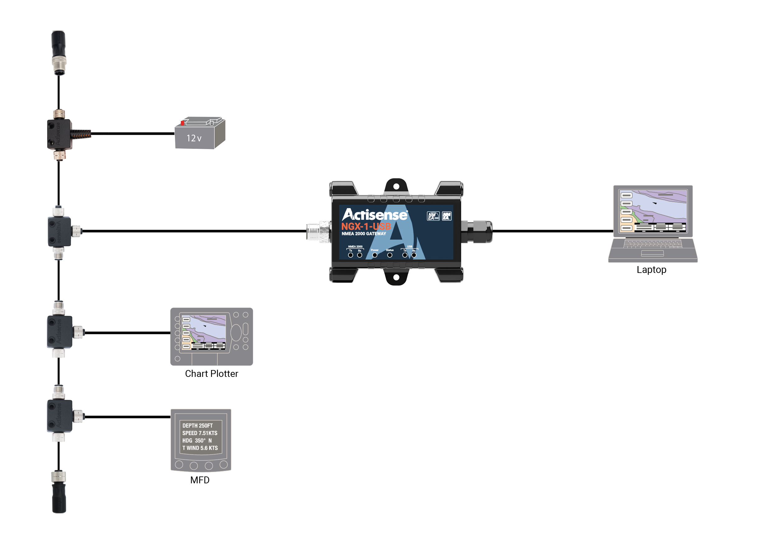
2. Use PC Gateways to view live network data
A PC interface device or gateway is extremely helpful for identifying data-related issues.
Which gateways to use
These gateways feed data into a PC running a terminal or NMEA monitoring programme, allowing you to check:
- Missing data
- Incorrect or incomplete sentences/PGNs
- Devices not transmitting
- Corrupted data
This makes it much easier to spot configuration issues. For example, a GPS not outputting the PGNs that the charplotter expects.
3. Split the network to identify faulty devices
If power and resistance check out, the next stop is systematic fault isolation.
The Half-Split method
- Disconnect half the backbone, and move the termination resistor to the new endpoint.
- Check if the issue still remains:
- If yes: the fault is in the half that’s still connected
- If no: the problem lies in the disconnected half
- Keep splitting until you narrow it to a single device or cable.
Once narrowed down
- Swap in t-pieces or cabling that are known to be good
- Inspect field fit connectors for wiring errors
- If necessary, check internal connections (only with manufacturer approval to avoid potentially voiding warranty)
- If all else fails, the device itself is likely faulty – contact the manufacturer

Additional recommended tools
Wireless gateways
A wireless gateway (such as the Actisense W2K-2 NMEA 2000 to Wi-Fi Gateway) lets you monitor your NMEA 2000 network from anywhere onboard. Benefits include:
- Data logging via SD card* (acts like a voyage data recorder)
- Post-voyage analysis
- Historical logs for incident investigation
*SD Card is not included in the W2K-2
Actisense-i diagnostic features
With the Actisense W2K-2 and WGX-1, Actisense-i provides enhanced diagnostics:
- Voltage monitoring
- Device list
- Transmit/receive load
- PGN visibility per device
- Ability to spot invalid or missing data instantly

This deeper insight often reveals configuration issues, like a GPS not outputting the expected PGNs. This allows the user to not only see which devices are on the bus, but also every bit of data, offering improved diagnostics by improving data visibility. These features enable technicians to investigate a network to see if devices are transmitting invalid data, or perhaps aren’t transmitting at all.
Often, a fault report of ‘I’ve got no GPS data on my chartplotter’ is because the GPS hasn’t been configured to output all of the data the user wants. Whilst this gives the illusion that the GPS isn’t working, more often than not, the GPS is fine, but the configuration is wrong. Data insights allow us to see what PGNs are being sent by the GPS, which means we can determine if the data is present on the network or not. If it is, and the chartplotter isn’t displaying it, then it’s usually that the chartplotter config/source selection is incorrect.
Summary
By combining simple checks, live monitoring, and systematic network isolation, you can diagnose the vast majority of NMEA issues quickly and confidently. With tools like multimeters, PC gateways, and modern wireless diagnostics, it’s easier than ever to pinpoint faults, verify configuration, and keep your onboard network performing reliably.
 3 common mistakes when installing NMEA devices
  Interfacing your NMEA 0183 and NMEA 2000 marine electronics with an onboard computer
  3 fundamentals for building a fault free NMEA 2000 network